
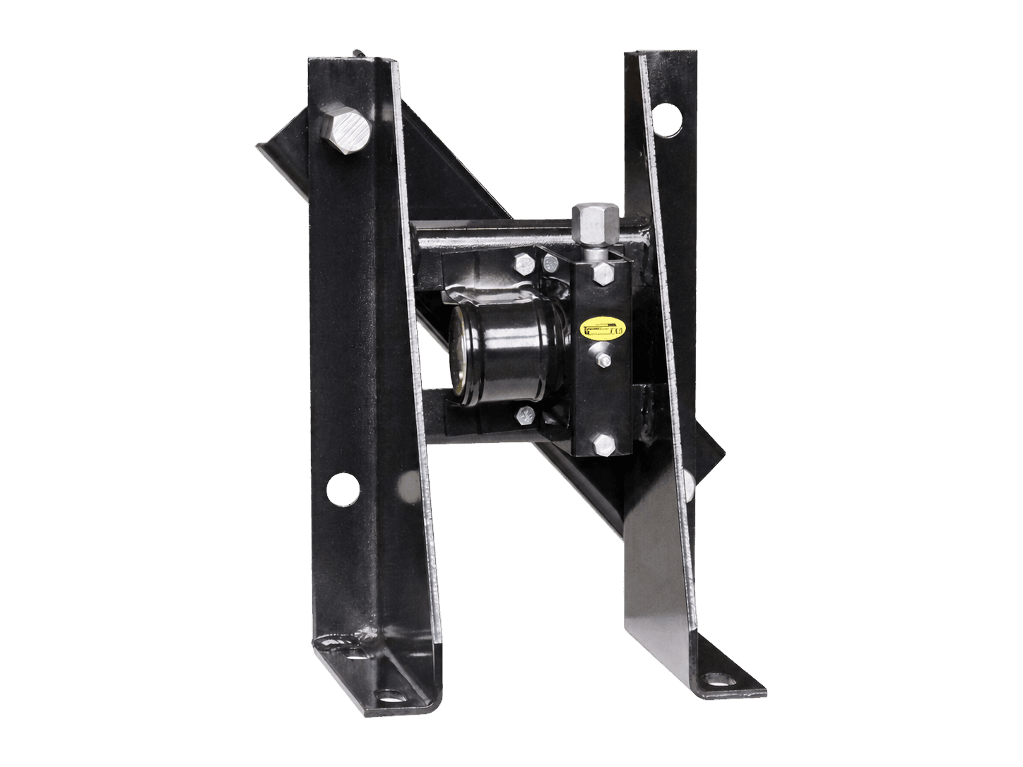
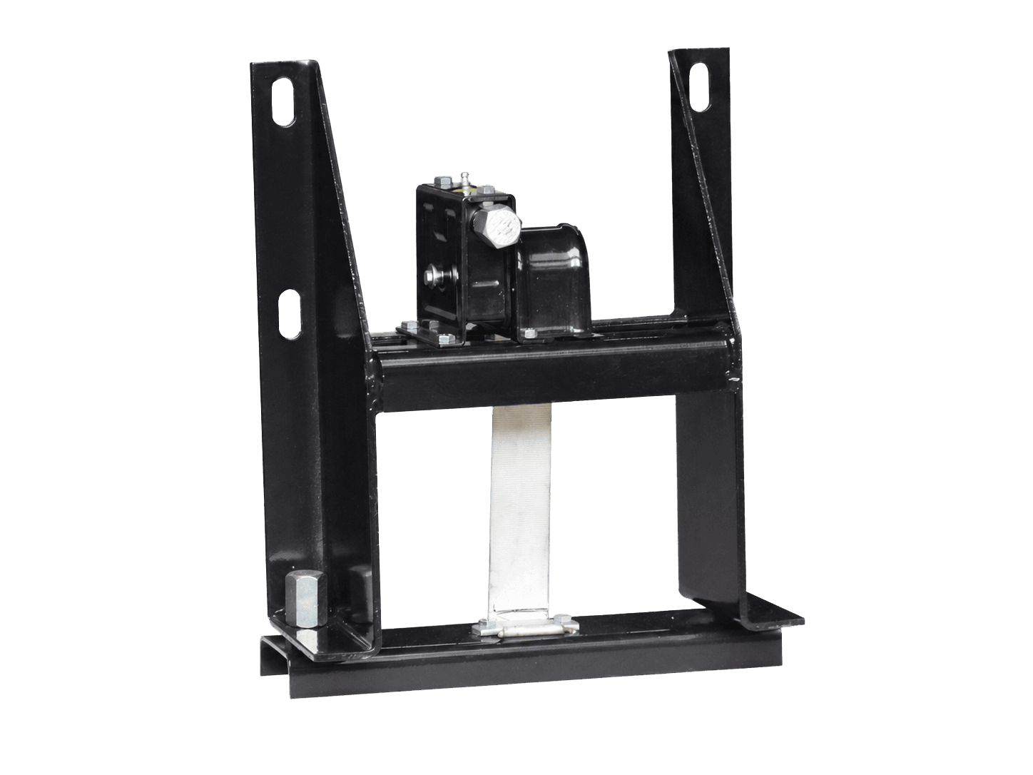
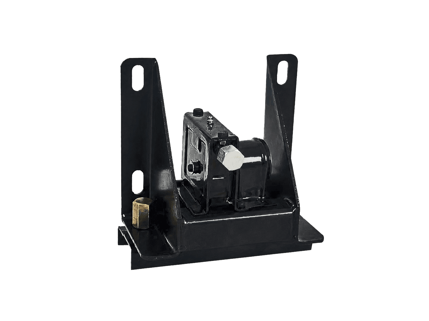
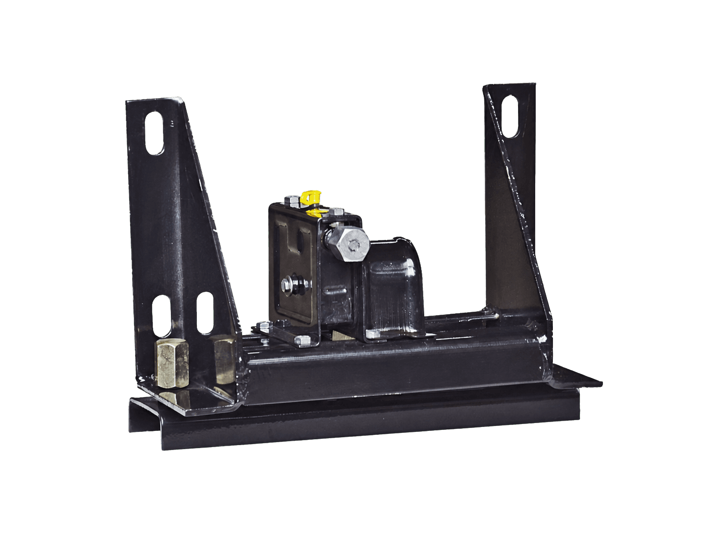
What the TMS-111 is designed to do
The TMS-111 belongs to the spare wheel carrier product group and uses a truck-type carrier arrangement. Its purpose is to retain a spare wheel in a designated chassis-mounted position rather than leave the wheel unsecured in the vehicle body, cargo area or workshop environment. The carrier is therefore considered part of the vehicle’s equipment layout and should be assessed alongside the chassis, wheel and surrounding components.
In a typical truck configuration, the carrier may form part of the wider spare wheel storage system. Its suitability depends not only on the carrier itself, but also on the intended wheel, the available clearance and the selected mounting location. The product information identifies it as a chassis-mounting solution; exact dimensions, fixing details and vehicle-specific suitability are not defined in the available data and should be verified with the technical team.
Where it fits in the vehicle workflow
For vehicle builders and body manufacturers, a spare wheel carrier is normally considered during chassis planning, body installation or equipment renewal. The selected location must allow the wheel to be installed and removed without conflicting with the frame, bodywork, suspension-related components, axles, exhaust routing or other equipment. Access should also be considered in relation to the workshop procedures used during roadside or scheduled maintenance.
For fleet operators and repair workshops, the TMS-111 can be relevant when an existing spare wheel arrangement needs replacement or when a chassis requires a dedicated mechanical carrier. Before ordering, identify the truck chassis and the intended installation area rather than relying only on the general description of a truck-type carrier. A carrier that is suitable for one chassis layout may require a different arrangement, mounting position or project review on another vehicle.
Selection and compatibility checks
The first selection check is the relationship between the spare wheel and the carrier location. Confirm the wheel and tyre assembly intended for transport, the space available around the chassis and the route needed for fitting and removal. The mounting position should be reviewed for interference with body structures, chassis members and operating equipment. These checks help establish whether the proposed installation is physically feasible before detailed fitting work begins.
Compatibility must be confirmed against the actual vehicle rather than inferred from the product code. Provide the chassis or vehicle identification, relevant drawings or photographs, the planned mounting side or position, and information about the spare wheel. If the carrier is being used in a modification or renewal project, also describe the existing arrangement and any changes to the body or chassis. Where any detail is uncertain, ask the technical team to review the application before purchase.
Installation and inspection context
Installation should be carried out using a suitable chassis mounting method and according to the approved project arrangement. The mounting area should be checked for clear access, adequate space and possible interference before the carrier is fixed in place. Since the available product facts do not specify fixing dimensions, fastener requirements, installation torque or vehicle-specific procedures, these details must not be assumed and should be confirmed for the particular application.
After installation, inspect the carrier and its mounting arrangement as part of the vehicle build or workshop handover. Check that the spare wheel is correctly retained, that the mechanism can be operated as intended and that the stored wheel does not contact nearby components during normal vehicle use. The inspection should also confirm that the carrier does not obstruct access to other service points or create an unintended conflict with the body, chassis or adjacent equipment.
Maintenance observations and precise enquiries
Maintenance personnel should include the spare wheel carrier in routine visual checks of the chassis-mounted equipment. Look for looseness, visible damage, deformation, unusual movement, corrosion or contamination that could affect operation or retention. Keep the carrier and its operating area reasonably clear, and investigate any change in movement or wheel security before the vehicle returns to service. Specific lubrication intervals and service procedures are not provided here, so they should be established from the applicable technical documentation.
A precise enquiry helps the technical team assess the TMS-111 for the intended use. Include the product code, vehicle or chassis details, spare wheel and tyre information, proposed mounting location, available clearance and whether the request concerns a new build, replacement or repair. Photos, drawings and measurements of the surrounding chassis area can further clarify the application. The final compatibility decision should be based on these project details and technical confirmation, not on the product category alone.